Posts

Showing posts from November, 2023

YD-ESP32-S3-EYE/CircuitPython 8, control LCD and Camera.

Image
With CircuitPython 8.2.8 installed on YD-ESP32-S3-EYE ,  Here are exercises to access LCD and camera on YD-ESP32-S3-EYE . Exercise to test LCD/Color on LCD, cpyS3EYE_LCD_color.py . """ LCD/Color test on YD-ESP32-S3-EYE/CircuitPython 8.2.8 """ import os, sys import board import time import displayio import terminalio from adafruit_display_text import label display = board.DISPLAY #======================================= info = os.uname()[4] + "\n" + \ sys.implementation[0] + " " + os.uname()[3] + "\n" + \ "board.DISPLAY: " + str(display.width) + "x" + str(display.height) print("=======================================") print(info) print("=======================================") print() # Make the display context bgGroup = displayio.Group() display.show(bgGroup) bg_bitmap = displayio.Bitmap(display.width, display.height, 1) # with one color bg_palette = displayio.Palett
My Raspberry Pi 5/8G and Camera Modules

Image
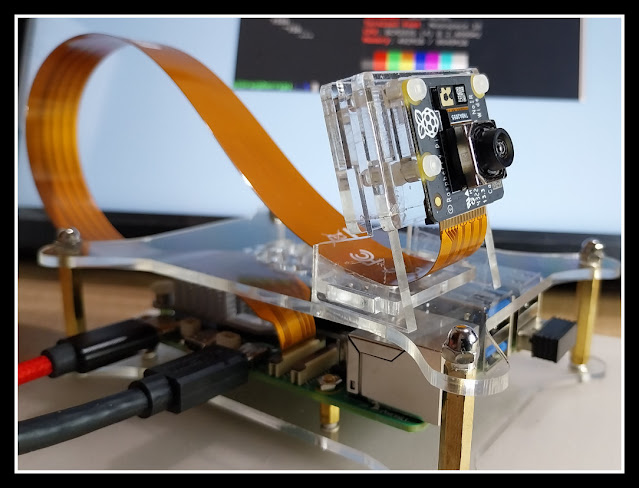
My Raspberry Pi 5/8G & Camera Module 3 Wide NoIR Raspberry Pi 5 with dual camera, Camera Module 3 & HQ Camera. Official document: ~ The Picamera2 Library (picamera2-manual.pdf) updated at 2023-11-27. ~ Raspberry Pi Camera Algorithm and Tuning Guide (raspberry-pi-camera-guide.pdf) updated at 2023-11-27. Python code to read sys info: ~ check memory and disk info using psutil ~ read model name ~ Python code to check if Raspberry OS are Running in 32-bit or 64-bit Exercises run on Raspberry Pi 5 running 64-bit Raspberry Pi OS (bookworm) with Camera Module 3: ~ Python/picamera2 to read camera properties ~  Using the Raspberry Pi Camera in Python3/PyQt5 applications using picamera2 lib ~  Python/PyQt5 GUI to control Raspberry Pi Camera using picamera2 lib , with Camera Module 3/HQ Camera. ~  Python/PyQt5/Picamera2 to control Raspberry Pi Cameras with GUI, with camera_controls . ~  Python/PyQt5/Picamera2 to control Raspberry Pi Ca

Install CircuitPython firmware on YD-ESP32-S3-EYE using esptool

Image
Install CircuitPython 8.2.8 firmware on YD-ESP32-S3-EYE by VCC-GND Studio using esptool, run on Linux Mint 21.2, over Windows 11/VirtualBox. Power up in BOOTLOADER mode: - Press and hold BOOT button, connect USB. Visit CircuitPython Download Page , search and download for ESP32-S3-EYE. Download .BIN of CircuitPython 8. Check CHIP/FLASH ID: esptool.py --chip auto --port <PORT> chip_id esptool.py --chip auto --port <PORT> flash_id Erase Flash:: esptool.py --chip esp32s3 --port <PORT> erase_flash Flash Firmware in .BIN: esptool.py --chip esp32s3 --port <PORT> --baud 460800 write_flash -z 0x0 <.BIN> Disconnect and connect USB again. It will run in CircuitPython. Exercises of CircuitPython run on YD-ESP32-S3-EYE: ~  YD-ESP32-S3-EYE/CircuitPython 8, control LCD and Camera .

Flash CircuitPython 9 (Alpha 5) on ESP32-C6, and control on-board RGB LED (NeoPixel).

Image
Flash CircuitPython 9.0.0-alpha.5 on YD-ESP32-C6-N16 , and control on-board RGB LED (NeoPixel). Run on Windows 11. esptool is needed to flash firmware on ESP-C6, read  Install esptool on Windows 11 . Steps to flash CircuitPython firmware on ESP32-C6: Visit https://circuitpython.org/downloads , search boards of ESP32-C6. There are no 16MB Flash version, so I try "ESP32-C6-DevKitC-1-N8". Download .bin of CircuitPython 9.0.0-alpha.5 now. Connect to USB connector marked "COM". Erase Flash with command: esptool --chip esp32c6 --port <COM> erase_flash Write Binary Data to Flash with command: esptool --chip esp32c6 --port <COM> write_flash 0x0 <.bin> Reconect USB to connector marked "USB". Open Thonny Python IDE. In Thonny: > Run > Configure interpreter... Select interpreter of "CircuitPython (generic)" and Port, then OK. Prepare lib for neopixel: Visit https://circuitpython.org/libr

Raspberry Pi Pico/TFT_eSPI display on 3.5" 480 x 320 ILI9488 SPI TFT

Image
This video show  Raspberry Pi Pico (RP2040) using TFT_eSPI library display on 3.5" 480 x 320 ILI9488 SPI TFT , in Arduino Framework. Install TFT_eSPI in Arduino IDE's Library Manager. It's strongly suggested to visit TFT_eSPI page , scroll down to Tips section. If you load a new copy of TFT_eSPI then it will overwrite your setups if they are kept within the TFT_eSPI folder. One way around this is to create a new folder in your Arduino library folder called "TFT_eSPI_Setups". You then place your custom setup.h files in there. After an upgrade simply edit the User_Setup_Select.h file to point to your custom setup file. To locate Arduino library folder: > File > Preferences... Copy the path inside Sketchbook location. Open file explorer to open Sketchbook location, to locate Arduino library folder. Create a new folder in your Arduino library folder called "TFT_eSPI_Setups". Copy the file /TFT_eSPI/User_Se

Check if I belongs to dialout group (Linux command)

Image
Tested on Linux Mint 21.2, to check if I belongs to any group, Linux command id and groups can be used. id: Print user and group information for each specified USER, or (when USER omitted) for the current user. id id <user> groups: Print group memberships for each USERNAME or, if no USERNAME is specified, for the current process (which may differ if the groups database has changed). groups groups <user>

Display on 320x480 ILI9488 SPI TFT with Nano 33 BLE nRF52840 using Arduino_GFX Library (Arduino framework)

Image
This video show steps to display on 3.5" 320x480 ILI9488 SPI TFT with Nologo Nano 33 BLE nRF52840 using Arduino_GFX Library (Arduino framework). Makesure "GFX Library for Arduino" is installed in Arduino IDE Library Manager. Open Examples > GFX Library for Arduino > HelloWorldGfxfont Replace the code of Arduino_GFX setting, /******************************************************************************* * Start of Arduino_GFX setting ******************************************************************************/ #include <Arduino_GFX_Library.h> #define TFT_CS D10 #define TFT_RESET D9 #define TFT_DC D8 #define TFT_MOSI D11 #define TFT_SCK D13 #define TFT_LED D7 #define TFT_MISO -1 // not used for TFT #define GFX_BL TFT_LED // backlight pin /* More data bus class: https://github.com/moononournation/Arduino_GFX/wiki/Data-Bus-Class */ Arduino_DataBus *bus = new Arduino_HWSPI(TFT_DC, TFT_CS); /* More display c

Install Espressif IDF Extension in VS Code to program ESP32-C3 Run on Linux Mint 21.2 (over Windows 11/VirtualBox)

Image
This video show steps to install Espressif IDF Extension in VS Code to program Espressif ESP32-C3-DevKitM-1 . Here VS Code run on Linux Mint 21.2 (over Windows 11/VirtualBox) . Basically, it follow the steps in  ESP-IDF Visual Studio Code Extension Installation Guide to - Install ESP-IDF Extension to VS Code. - Install Prerequisites for Linux . - Configure ESP-IDF extension. - Add 60-openocd.rules for permisssion delegation in USB to added in /etc/udev/rules.d/. Then follow Basic use of the extension to: - Create project of Blink example. - Grant permission to user to access USB port. - finally flash on ESP32-C3-DevKitM-1. Fix IntelliSense error of: identifier "CONFIG_BLINK_PERIOD" is undefined identifier "portTICK_PERIOD_MS" is undefined in VS Code/ESP-IDF Blink Example. With auto-generated code with default setting, it can be built, flash and run on ESP32-C3 device without error. Is it OK, ...NOT. If you open main/b