Posts

Showing posts from September, 2022

XIAO nRF52840 Sense/XIAO Expansion board display on OLED in Arduino framework, using U8g2 Library.

Image
With  Seeed nRF52 Boards installed on Arduino IDE , this video show how 128x64 I2C OLED (SSD1306/SSD1315) displayed on  XIAOnRF52840 Sense and XIAO Expansion board . Make sure U8g2 is installed in Arduino IDE. Open Examples > U8g2 > full_buffer > GraphicsTest Uncomment the contructor U8G2_SSD1306_128x64_NONAME_F_HW_I2C using hardware I2C 128x64 SSD1306 driver. ~ more exercise to drive SSD1306 using U8g2, refer to the post " Xiao ESP32C3 display on SSD1306 128x64 OLED (I2C & SPI) using U8g2 Library ". next: ~  BLE UART Peripheral run on XIAO nRF52840 Sense (in Arduino Framework)

Install Seeed nRF52 Boards on Arduino IDE 1.8.19 to program XIAO nRF52840 Sense in Arduino Framework (on Raspberry Pi OS)

Image
To program  Seeed Studio XIAO nRF52840 Sense in Arduino Framework, we have to install "Seeed nRF Boards" and/or "Seeed nRF52 mbed-enabled Boards" in Arduino IDE. This video show steps to install Seeed nRF52 Boards on Arduino IDE 1.8.19 (on Raspberry Pi OS 32-bit buster). Click File in Arduino IDE MENU > Preferences add the follow link in Additional Boards Manager URLs box. https://files.seeedstudio.com/arduino/package_seeeduino_boards_index.json If you are reported error of: exec: "adafruit-nrfutil": executable file not found in $PATH You have to install adafruit-nrfutil, enter the command in terminal: $ pip3 install --user adafruit-nrfutil In my case, adafruit-nrfutil installed successfully but not on PATH. To add the installed directory to PATH, edit ~/.bashrc: $ nano ~/.bashrc Add following code in the end of .bashrc: PATH=${PATH}:<installed directory> export PATH In nano, Ctrl-X and answer Y and ENTER to accept

Xiao ESP32C3 display on SSD1306 128x64 OLED (I2C & SPI) using U8g2 Library

Image
Xiao ESP32C3  (arduino-esp32 framework) exercise to display 128x64 SSD1306 OLED, both I2C and SPI. Tested on  XIAO Expansion board ,  SSD1315 I2C OLED (SSD1306 compatible) and  SSD1306 SPI OLED . U8g2 Library is used to drive the OLEDs, make sure it's installed in Arduino IDE. Connection for SPI interface: OLED SPI Xiao ESP32C3 GND GND VCC 3V3 SCL GPIO8 SDA GPIO10 RST GPIO2 D/C GPIO3 for I2C interface: OLED I2C Xiao ESP32C3 GND GND VCC 3V3 SCL GPIO7 SDA GPIO6 Exercise Code: XiaoESP32C3_Serial_Terminal.ino Accept user input from Serial Monitor, and display on OLED as a terminal (U8X8LOG). /* * Read from Serial and display on * XIAO Expansion board I2C SSD1306 OLED (128x64) * using U8g2 library. * In this exercise, the OLED act as a terminal (U8X8LOG). */ #include <Arduino.h> #include <U8x8lib.h> #ifdef U8X8_HAVE_HW_SPI #include <SPI.h> #endif // U8x8 Contructor U8X8_SSD1306_128X64_NONAME_HW_I2C u8x8(/* reset=*/ U8X8_PIN_NONE

Raspberry Pi Pico W/MicroPython connect to WiFi network and synchronize to NTP Time Server

Image
Exercise run on  Raspberry Pi Pico W with  MicroPython v1.19.1 , connect to WiFi network and synchronize to NTP Time Server. mpyPicoW_toConnect_ntptime.py """ MicroPython/Pico W connect to WiFi using network.WLAN once connected, synchronize with NTP Time Server using ntptime ref: https://docs.micropython.org/en/latest/library/network.WLAN.html """ import time import network import machine import ubinascii import sys import os import ntptime ssid = "ssid" password = "password" # Flash onboard LED three times to indicate program start led = machine.Pin("LED", machine.Pin.OUT) for l in range(3): led.off() time.sleep(0.3) led.on() time.sleep(0.3) led.off() print("=========================================================") print(sys.implementation[0], os.uname()[3], "\nrun on", os.uname()[4]) print("=========================================================") print(

Free ebook - The Picamera2 Library Manual

Image
Picamera2 is the libcamera-based replacement for Picamera which was a Python interface to the Raspberry Pi's legacy camera stack. Picamera2 also presents an easy to use Python API. Picamera2 is currently available as a beta release. This means there may still be some issues and bugs which shall be worked on fixing, and where users identify particularly useful features may still be considered implementing them. ~ Download The Picamera2 Library Manual (PDF)

Online books for Embedded Rust

Image
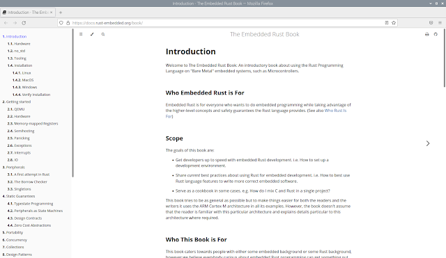
Rust Embedded aims to be a resource for Rust programmers writing software for embedded devices. The Embedded Rust Book is an introductory book about using the Rust Programming Language on "Bare Metal" embedded systems, such as Microcontrollers. Another one  Discover the world of microcontrollers through Rust! There are currently two versions of this book. The first is older and uses an F3 Discovery circuit board to introduce you to microcontrollers and Rust, while the second is newer and uses a micro:bit circuit board instead. ~  Older book, using an F3 discovery board ~  Newer book, using a micro:bit

Raspberry Pi Pico W first power up and install MicroPython firmware

Image
This video show first power up Raspberry Pi Pico W and install MicroPython firmware on it. To download MicroPython firmware (in UF2 form) for Raspberry Pi Pico W, visit: https://www.raspberrypi.com/documentation/microcontrollers/micropython.html#drag-and-drop-micropython or from MicroPython page here:  https://micropython.org/download/rp2-pico-w/ New Pico W come with empty Flash memory, and boot up in BOOTSEL mode. So I can drag-and-drop the MicroPython UF2 file to Pico W directly. If your Pico W is not in BOOTSEL mode, you can hold down the BOOTSEL button when you plug in your Pico, it will appear as a drive onto which you can drag a new UF2 file. or, you can restore factory flash memory with flash_nuke.uf2 HERE . Exercise of MicroPython on Raspberry Pi Pico W: ~  connect to WiFi network and synchronize to NTP Time Server

Raspberry Pi Pico W

Image
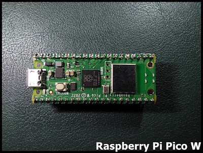
My dev.board -  Raspberry Pi Pico W pinout: ref: ~ The official documentation for Raspberry Pi microcontrollers ~ Raspberry Pi Pico W Datasheet ~  Connecting to the Internet with Raspberry Pi Pico W Related post: ~  Raspberry Pi Pico W first power up and install MicroPython firmware ~  MicroPython/CircuitPython, enter bootloader programmatically, without BOOT button. (Tested on Raspberry Pi Pico) Exercises of Pico W with MicroPython: ~  connect to WiFi network and synchronize to NTP Time Server ~  Raspberry Pi Pico W/MicroPython x 0.96" 80x160 ST7735 SPI IPS ~  Raspberry Pi Pico W/MicroPython act as socket client, connect to HC-25 WiFi Module . ~  Prepare MicroPython Bluetooth service example on Raspberry Pi Pico W (MicroPython v1.20.0 ) ~  MicroPython bluetooth example using aioble library, between Raspberry Pi Pico W and ESP32-C3. (Both run MicroPython 1.21.0) ~  MicroPython bluetooth remote control LED between Raspberry Pi Pico W and ESP32-C3, using aioble

Nano RP2040 Connect get time from Network Time Protocol (NTP) time server display on ST7789 SPI IPS

Image
The Network Time Protocol (NTP) is a networking protocol for clock synchronization between computer systems over packet-switched, variable-latency data networks. ~ ref: wikipedia.org>Network_Time_Protocol To get time from Network Time Protocol (NTP) time server using Arduino Nano RP2040 Connect With WiFiNINA library installed in Arduino IDE's Library Manager, it a sample WiFiUdpNtpClient show how to get the time from a Network Time Protocol (NTP) time server, demonstrates use of UDP sendPacket and ReceivePacket. Display on 1.14" 135x240 ST7789 SPI IPS Read here for Nano RP2040 Connect to display on 1.14" 135x240 IPS ST7789 SPI in Arduino Framework . Exercise code to get time from Network Time Protocol (NTP) time server display on ST7789 SPI IPS NRP_WiFiUdpNtpClient.ino /* * Arduino Nano RP2040 Connect query NTP TIme Service (base on WiFiNINA example WiFiUdpNtpClient), * display on 1.14" 135x240 ST7789 SPI IPS. *

Get info of XIAO ESP32C3 (Arduino)

Image
XiaoESP32C3_info.ino , Arduino code to read info of XIAO ESP32C3 . #include <Esp.h> void setup() { delay(500); Serial.begin(9600); delay(500); Serial.println("\n\n================================"); Serial.println("Seeed Studio XIAO ESP32C3"); Serial.println("================================"); Serial.printf("Chip Model: %s\n", ESP.getChipModel()); Serial.printf("Chip Revision: %d\n", ESP.getChipRevision()); Serial.printf("with %d core\n", ESP.getChipCores()); Serial.printf("Flash Chip Size : %d \n", ESP.getFlashChipSize()); Serial.printf("Flash Chip Speed : %d \n", ESP.getFlashChipSpeed()); esp_chip_info_t chip_info; esp_chip_info(&chip_info); Serial.printf("\nFeatures included:\n %s\n %s\n %s\n %s\n %s\n", (chip_info.features & CHIP_FEATURE_EMB_FLASH) ? "embedded flash" : "", (chip_info.features & CHIP_FEATURE_

Seeed Studio XIAO ESP32C3

Image
 My dev.board -  Seeed Studio XIAO ESP32C3 pinout: ref: ~  Getting Started with Seeed Studio XIAO ESP32C3 Exercise on Arduino Framework: ~  Get info of XIAO ESP32C3 ~  display on SSD1306 128x64 OLED (I2C & SPI) using U8g2 Library ~  BLE UART Communication between XIAO ESP32C3 (client/central) and nRF52840 (server/peripheral), in Arduino Framework . ~  Read TMP102 (I2C Temperature Sensors) with XIAO ESP32-C3 ~  480x320 TFT/ILI9488 SPI wih EP32C3 (arduino-esp32) using Arduino_GFX Library ~  128x160 TFT/ST7735 SPI wih EP32C3 (arduino-esp32) using Arduino_GFX Library . for CicuitPython: ~ Flash CircuitPython firmware to ESP32-S3/C3 using esptool on Windows 11 ~  ESP-NOW on CircuitPython 9.0.3, tested on ESP32-S3/ESP32-C3 .

Free ebok - Raspberry Pi Handbook 2023

Image
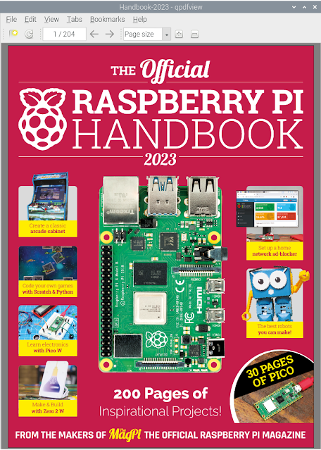
 Download  The Official Raspberry Pi Handbook 2023 HERE for Free.

Nano RP2040 Connect (in Arduino Framework) connect to WiFi network

Image
This Arduino exercise run on Nano RP2040 Connect with WiFiNINA library, to connect to WiFi network. If connection lost, it will try to re-connect again. The onboard LED indicate the connection status. Library need: Install WiFiNINA in Arduino IDE Library Manager. Code:  NRP_toConnect.ino //"WiFiNINA by Arduino" needed to be installed in Arduino IDE Library Manager #include <WiFiNINA.h> int status = WL_IDLE_STATUS; char ssid[] = "ssid"; // your network SSID (name) char pass[] = "password"; // your network password (use for WPA, or use as key for WEP) int keyIndex = 0; // your network key index number (needed only for WEP) unsigned long previousMillis; const long interval = 1000; //interval for 1 second void setup() { delay(500); Serial.begin(9600); delay(500); while (!Serial) { ; // wait for serial port to connect. Needed for native USB port only } Serial.println("\n--- Start ---

Capture screen in Raspberry Pi OS, gnome-screenshot

Image
gnome-screenshot is my favorite program in Raspberry Pi OS to capture screen. To install gnome-screenshot in Raspberry Pi OS: $ sudo apt install gnome-screenshot After installed, it's located in Accessories > Screenshot

Query if a package is installed or installable using apt-cache command

Image
In Raspberry Pi OS (or Linux), apt-cache queries and displays available information about installed and installable packages. example: to query if gnome-screenshot is available to install $ apt-cache search gnome-screenshot

Arduino Nano RP2040 Connect display on 1.14" 135x240 IPS ST7789 SPI (in Arduino Framework)

Image
Arduino Nano RP2040 Connect display on 1.14" 135x240 IPS ST7789V SPI (in Arduino Framework), using Adafruit ST7735 and ST7789 Library. The default SPI pins of Nano RP2040 Connect in Arduino Framework is: SS:          D10 MOSI:    D11 MISO:    D12 SCK:      D13 Connection using Hardware SPI:      ST7789V(SPI)      Nano RP2040 Connect      GND      GND      VCC      3V3      SCL      D13 (default SCK)      SDA      D11 (default MOSI)      RES      D10      DC      D9      CS      D8      BLK      3V3 Nano RP2040 Connect ST7789 SPI +---------------------+ +------ |      | GND-| GND | +--------------+ | 3V3-| VCC +--| D13      D12 | +---------| SCL 3V3-| 3V3 D11 |-------------| SDA | D10 |-------------| RES | D9 |-------------| DC | D8 |-------------| CS | | 3V3-| BLK | | +------- | | | | | | | | | | | | GND

1.14" 135x240 (RGB) IPS ST7789V SPI SKU:MSP1141

Image
My display module - 1.14" 135x240 (RGB) IPS ST7789V SPI Product Page - LCD WiKi - SKU:MSP1141 ~  Arduino Nano RP2040 Connect display on 1.14" 135x240 IPS ST7789V SPI (in Arduino Framework) ~  Nano RP2040 Connect get time from Network Time Protocol (NTP) time server display on ST7789 SPI IPS ~  ESP32-S3/CircuitPython 8 display on ST7789 SPI TFT ~  Play animated GIF in CircuitPython 8.1.0 Beta 0, run on ESP32-S3, display on ST7789 SPI TFT .

mini 13.56MHZ MFRC522 RC522 RFID Module

Image
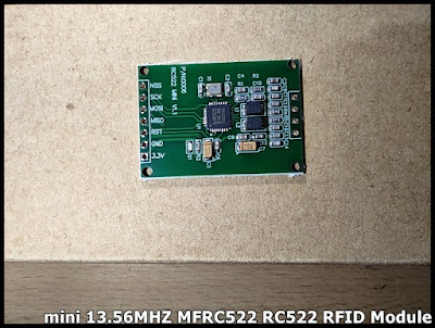
My RFID Module - mini 13.56MHZ MFRC522 RC522 RFID Module

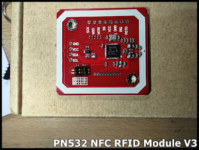
Elechouse PN532 NFC RFID Module V3

Image
My RFID Module - Elechouse PN532 NFC RFID Module V3 Product page ~ Newer version of Elechouse PN532 NFC RFID Module V4 Please note: V4 is completely compatible with V3 on hardware and software. V4 keeps exactly the same shape, installing holes and interface as V3. Due to improved PCBA design and assembly technology, PN532 NFC V4 performs much better than V3.

Arduino IDE on Raspberry Pi OS can't compile for RP2040 - Error loading Python lib libpython3.7m.so.1.0

Image
For Arduino IDE running on Raspberry Pi OS 32-bit buster, with Arduino Mbed OS Nano Boards (for Arduino Nano RP2040 Connect) and Arduino Mbed OS RP2040 Boards (for Raspberry Pi Pico) installed, after updated to version 3.0.0 or higher, it cannot compile caused by Error loading Python lib libpython3.7m.so.1.0. [12810] Error loading Python lib '/tmp/_MEIuqNZik/libpython3.7m.so.1.0': dlopen: /tmp/_MEIuqNZik/libpython3.7m.so.1.0: cannot open shared object file: No such file or directory exit status 255 /home/pi/arduino/arduino-builder returned 255 Error compiling for board Arduino Nano RP2040 Connect. For temporary, my solution is to rollback to version 2.8.0.