Posts

Showing posts from February, 2024

Radar-like distance scanner on ESP32-S3/CircuitPython 9, using SG90 servo motor, VL53L0X distance sensor and SSD1306 OLED.

Image
With previous exercises of SSD1306 I2C OLED ,  VL53L0X distance sensor and SG90 servo motor run on ESP32-S3-Zero with CircuitPython 9.0.0-beta.0 installed . The following exercise implement a Radar-like distance scanner. cpy_C3-Zero_ssd1306_fb_servo_scanner.py """ CircuitPython 9.0.0-beta.0 exercise run on Waveshare ESP32-S3-Zero: - drive servo moto SG90 using adafruit_motor - detect distance using using adafruit_vl53l0x - display on SSD1306 I2C OLED using adafruit_ssd1306 lib needed: - adafruit_framebuf.mpy - adafruit_simplemath.mpy - adafruit_ssd1306.mpy - adafruit_vl53l0x.mpy - adafruit_motor folder """ import os import sys import board import busio import time import math import adafruit_ssd1306 import pwmio from adafruit_motor import servo import adafruit_vl53l0x from adafruit_simplemath import map_range # create a PWMOut object on Pin A2. pwm = pwmio.PWMOut(board.IO7, duty_cycle=2 ** 15, frequency=50) # Create a serv
CircuitPython exercise to control servo motor, run on ESP32-S3-Zero/CircuitPython 9.0.0-beta.0.

Image
CircuitPython exercise to control servo motor SG90, run on ESP32-S3-Zero / CircuitPython 9.0.0-beta.0 . cpyS3Zero-servo.py """ CircuitPython exercise to control servo motor run on ESP32-S3-Zero/CircuitPython 9.0.0-beta.0 ref: https://learn.adafruit.com/circuitpython-essentials/circuitpython-servo https://learn.adafruit.com/using-servos-with-circuitpython/circuitpython lib needed: - adafruit_motor folder Connection: (a external 5V power source is used for servo motor) Ext.5V Servo ESP32-S3-Zero ---------------------------------------- GND GND(Brown) GND +5V V+(Red) Signal(Yellow) IO7 """ import os, sys import time import board import pwmio from adafruit_motor import servo pin_signal = board.IO7 # create a PWMOut object on Pin GPIO7. pwm = pwmio.PWMOut(pin_signal, duty_cycle=2**15, frequency=50) # Create a servo object, my_servo. my_servo = servo.Servo(pwm, min_pulse=500, max_pulse=2500) print(&

Solve FutureWarning: I2CDisplay moved from displayio to i2cdisplaybus and I2CDisplay renamed I2CDisplayBus

Image
In CircuitPython 8 and before, I2CDisplay is in displayio . In CircuitPython 9+, it's moved to i2cdisplaybus.I2CDisplayBus . This exercise define display_bus in try:...except ImportError:...block, using displayio.I2CDisplay on CircuitPython 8, and i2cdisplaybus.I2CDisplayBus on CircuitPython 9. rp2040_ssd1306_displayio_circuitpython89.py """ Solve: FutureWarning: I2CDisplay moved from displayio to i2cdisplaybus FutureWarning: I2CDisplay renamed I2CDisplayBus In CircuitPython 8 and before, I2CDisplay is in displayio (https://docs.circuitpython.org/en/8.2.x/shared-bindings/displayio/index.html#displayio.I2CDisplay). In CircuitPython 9+, it's moved to i2cdisplaybus.I2CDisplayBus (https://docs.circuitpython.org/en/latest/shared-bindings/i2cdisplaybus/index.html#i2cdisplaybus.I2CDisplayBus). This exercise define display_bus in try:...except ImportError:...block, using displayio.I2CDisplay on CircuitPython 8, and i2cdisplaybus.I2CDisplayBus on Ci

Rust on ESP (esp-rs), toggle GPIO to control LED on ESP32-C6.

Image
With Embedded Rust for ESP32 installed on Linux Mint 21.3 over VirtualBox/Windows 11 , this video show steps to run esp-rs on YD-ESP32-C6-N16 , toggle GPIO to control LED. Connect a LED and resistor (for current limit) between 3V3 and GPIO15 of ESP32-C6 board YD-ESP32-C6-N16 |      | |      | +-------| GPIO15      | | |      | | |                        | | |                     3.3V|---+ | +-------------------+ | |           | | | | | +-------|<|-----|/\/\/\|--------+ LED Resistor (current limit) Generate project: Generate a project based on esp-template(no_std): cargo generate esp-rs/esp-template - Project Name : rs-c6-blink - Target MCU : esp32c6 - false : not to configure advanced template options Edit /src/main.rs: #![no_std] #![no_main] use esp32c6_hal::{clock::ClockControl, peripherals::Peripherals, prelude::*, Delay, gpio::IO }; use esp_backtrace as _; use

Retrieve WiFi password in Windows 11

Image
To retrieve WiFi password in Windows 11: Enter the command in Command Prompt: netsh wlan show profiles name=<WiFi network> key=clear

SSD1306 I2C OLED + 4X4 Matrix Keypad Module on RP2040/CircuiyPython 9

Image
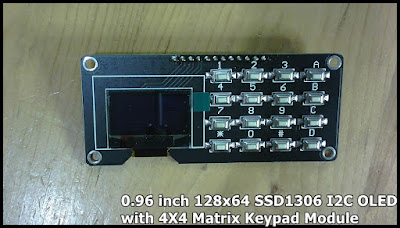
Exercises run on WeAct Studio Pico (rp2040) running CircuitPython 9.0.0-beta.0 with 0.96 inch 128x64 SSD1306 I2C OLED with 4X4 Matrix Keypad Module , to display on OLED using using adafruit_displayio_ssd1306, and detect 4X4 key-matrix using Keypad Module. Libraries need: - adafruit_displayio_ssd1306.mpy - adafruit_display_text folder (If you don't know how to download CircuitPython library bundle and upload to CircuitPython device, read related post RP2040/CircuitPython display on SH1107 SPI OLED ) For SSD1306 I2C OLED: displayio.I2CDisplay  moved from displayio to i2cdisplaybus and renamed I2CDisplayBus. You will not find I2CDisplay in current latest CircuitPython 9 displayio . In CircuitPython 9, it is moved to i2cdisplaybus.I2CDisplayBus . Currently, if you use displayio.I2CDisplay in CircuitPython 9 (actually it will be switched to I2CDisplayBus), it will not raise error, but raise warning: FutureWarning: I2CDisplay moved from displayio to i2

my display module: 0.96 inch 128x64 SSD1306 I2C OLED with 4X4 Matrix Keypad Module

Image
0.96 inch 128x64 SSD1306 I2C OLED with 4X4 Matrix Keypad Module ~  SSD1306 I2C OLED + 4X4 Matrix Keypad Module on RP2040/CircuiyPython 9

Hello CH32V307, flash & run GPIO_Toggle example on CH32V307V_EVT-R1, to blink LED and monitor USART.

Image
This video show how to flash & run GPIO_Toggle example on WCH CH32V307V_EVT-R1 using MounRiver Studio, to blink LED and monitor USART. Prepare CH32V307EVT evaluation board manual and reference routines Visit: https://www.wch.cn/products/CH32V307.html to download CH32V307评估板说明及参考应用例程 (CH32V307EVT evaluation board manual and reference routines): CH32V307EVT.ZIP Open GPIO_Toggle.wvproj with MounRiver Studio (under \CH32V307EVT\EVT\EXAM\GPIO\GPIO_Toggle folder), this example toggle PA0 and print something on USART. Connect USB to CH32V307V_EVT-R1: It's a built-in WCH-LinkE (same function as this one ) on CH32V307V_EVT-R1, used for online debugging and downloading of WCH RISC-V MCU, and also for online debugging and downloading of ARM MCU with SWD/JTAG interface. Connect USB to the USB port on the onboard WCH_LinkE of CH32V307V_EVT-R1. Configure WCH_LinkE: In MounRiver Studio, > Flash > Configuration. You can switch WCH_LinkE between WCH-Li

3-wire 9-bit SPI ST7789 TFT with FT6236 capacitive touch on ESP32-S3-Zero/CircuitPython

Image
This video show Waveshare ESP32-S3-Zero running CircuitPython 9.0.0-beta.0 , display on 1.54" 240x240 3-wire 9-bit SPI ST7789 TFT with capacitive touch driver FT6236G . About 9-bit SPI: The display module use ST7789 driver with 3-wire SPI, no DC pin. On CircuitPython (9.0.0-beta.0 in this exercise),  if the command (DC) pin is not specified, a 9-bit SPI mode will be SIMULATED by adding a data/command bit to every bit being transmitted, and splitting the resulting data back into 8-bit bytes for transmission. The extra bits that this creates at the end are ignored by the receiving device . ref:  https://docs.circuitpython.org/en/latest/shared-bindings/fourwire/index.html#fourwire.FourWire About fourwire library: Start from  CircuitPython 9.0.0 Alpha 2 : Split off parts of displayio into multiple modules: busdisplay, fourwire, epaperdisplay, i2cdisplaybus, paralleldisplaybus. The existing displayio hierarchy will still be available 9.x.x, but is depre