Posts

Showing posts from December, 2022

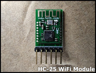
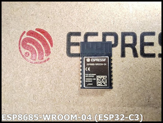
Xiao ESP32C3 (in arduino-esp32 framework) act as socket client, connect to HC-25 WiFi Module.

Image
Last post show my first test HC-25 WiFi Module, with AT Command; act as AP, setup socket server . Here is my exercise using Xiao ESP32C3 (in arduino-esp32 framework) to implement the client side: act as STA, join HC-25 WiFi network, connect to HC-25 socket server, receive and echo back in upper case. Exercise code: XiaoESP32C3_TCPclient.ino /* A simple TCP client run on ESP32-C3, * connect socket server run on HC-25 as AP. * * Have to set WAP in HC-25 using AT command: * AT+WMODE=AP * AT+WAP=myHC-25,password * * 192.168.4.1:8080 is the socket server on HC-25 */ #include <WiFi.h> // AP of HC-25 const char *ssid = "myHC-25"; const char *password = "password"; // server IP and port const IPAddress serverIP(192,168,4,1); uint16_t serverPort = 8080; WiFiClient client; void setup() { delay(200); Serial.begin(115200); delay(200); Serial.println("\n\r- Socket Client run on Xiao ESP32C3 (arduino-esp32) -"); Serial.printl

HC-25 WiFi Module

Image
HC-25 WiFi IoT module supports TCP, UDP, HTTP, MQTT ~ Product Page : include various information about HC-25 WiFi Module include Specification, AT Command Set, and various Utilities (currently in Chinese) First test HC-25 WiFi Module, with AT Command, as Socket Server: Once setup as in the video, the HC-25 act as AP (with ssid/password = "myHC-25"/"password", and setup socket server at 192.168.4.1:8080. Following are exercises to implement client side in various platform to connect to the HC-25 socket server: ~  Xiao ESP32C3 (in arduino-esp32 framework) act as socket client, connect to HC-25 WiFi Module . ~ Raspberry Pi Pico W/MicroPython act as socket client, connect to HC-25 WiFi Module . ~ ESP32-S3/CircuitPython act as socket client, connect to HC-25 WiFi Module .

80x160 ST7735S SPI TFT with Raspberry Pi Pico W/CircuitPython 8 Beta 5

Image
Display on 0.96" 80x160 (RGB) IPS with ST7735S SPI Driver with Raspberry Pi Pico W/CircuitPython 8.0.0 Beta 5 Prepare Libraries: Visit https://circuitpython.org/libraries , download and extract Bundle for Version 8.x matching with your CircuitPython version. Libraries need: adafruit_display_shapes folder adafruit_display_text folder adafruit_st7735r.mpy adafruit_ticks.mpy Copy to CircuitPython device's /lib  Connection: ST7735 Raspberry Pi Pico W --------------------------- BLK 3V3 CS GP15 DC GP14 RES GP13 SDA GP11 SCL GP10 VCC 3V3 GND GND Exercise Code: cpyPicoW_st7735r_simpletest.py modified from example st7735r_simpletest.py """ Copy from CircuitPython Lib example st7735r_simpletest.py """ # SPDX-FileCopyrightText: 2021 ladyada for Adafruit Industries # SPDX-License-Identifier: MIT """ This test will initialize the display using displayio and draw a solid green background, a smaller

0.96" 80x160 (RGB) IPS with ST7735S SPI Driver

Image
0.96" 80x160 (RGB) IPS with ST7735S SPI Driver ~ Product page Exercise: ~  80x160 ST7735S SPI TFT with Raspberry Pi Pico W/CircuitPython 8 Beta 5 ~  Raspberry Pi Pico W/MicroPython x 0.96" 80x160 ST7735 SPI IPS

CircuitPython 8.0.0 Beta 5 released with one-line status bar

Image
CircuitPython 8.0.0 Beta 5 released .  A one-line status bar added to displays connection status, last exception, and version on a terminal window title or on the top line of an attached display. It need Mu 1.2.0 or Thonny 4.0.x and later to suppress status bar information in the REPL output. Currently on Linux Mint 21, the Thonny available to be installed with apt is ver 3.3.14, not the most update 4.0.1. Refer last post " Install Thonny 4.0.1 on Linux Mint 21 ". Raspberry Pi Pico W with CircuitPython 8.0.0 Beta 5, work with Thonny 4.0.1. Work on Raspberry Pi Pico with CircuitPython 8.0.0 Beta 5, one-line status bar added on top of attached display ST7789.

Install Thonny 4.0.1 on Linux Mint 21

Image
Currently, the Thonny available to be installed with apt is ver 3.3.14, not the most update 4.0.1. To install Thonny 4.0.1 Visit Thonny page: https://thonny.org/ For Linux, download "thonny-4.0.1.bash", and make it runnable as program. Run in Terminal $ ./thonny-4.0.1.bash

ov2640 (Red board without MCLK) on Raspberry Pi Pico/CircuitPython (7 & 8 Beta)

Image
Run on Raspberry Pi Pico/CircuitPython 7.3.3 , capture images from ov2640 cam module (without MCLK) , display on ST7789 TFT. Develop on Raspberry Pi OS. Prepare Libraries: Visit https://circuitpython.org/libraries , download and extract library bundle match with your CircuitPython version. Libraries need: adafruit_st7789 and adafruit_ov2640, copy to CircuitPython device's /lib folder. Connection:      ST7789 SPI      +-------------- 3V3 | BLK GP1 | CS GP0 | DC GP4 | RES GP3 | SDA GP2 | SCL 3V3 | VCC GND | GND      +--------------      ov2640 (Red board without MCLK)      +-------------+ 3V3    | 3V3      GND | GND GP5 | VSYNC    SCL | GP17 * GP6 | HREF SDA | GP16 * GP7 | RST D0 | GP8 GP9 | D1      D2 | GP10 GP11 | D3      D4 | GP12 GP13 | D5      D6 | GP14 GP15 | D7      DCLK | GP18 N/C | NC      PWDN | N/C      +-------------+ *SCL/SDA are I2C-like interface, pull-up resistors are needed to

my cam.modules: ov7670 & ov2640

Image
ov7670:   ov2640: ov2640: Red board, without MCLK pin. remark: This ov2640 module have built-in 12M X'tal, so no MCLK pin in the header. Exercise: ~  ov2640 (Red board without MCLK) on Raspberry Pi Pico/CircuitPython (7 & 8 Beta)

Display on 240x320 ST7789 SPI IPS TFT using Raspberry Pi Pico/CircuitPython 7

Image
Steps to prepare libraries and code to display on 2.0" 240x320 (RBG) IPS w/ ST7789V2 SPI driver using Raspberry Pi Pico /CircuitPython 7.3.3. Visit https://circuitpython.org/libraries , download and extract library bundle match with your CircuitPython version. Copy adafruit_display_text folder and adafruit_st7789.mpy from /lib folder to CircuitPython device /lib folder. Copy st7789_320x240_simpletest.py from examples, name it cpyPico_st7789_320x240_simpletest.py. Edit for st7789 display on Raspberry Pi Pico, include pins connection. cpyPico_st7789_320x240_simpletest.py # SPDX-FileCopyrightText: 2021 ladyada for Adafruit Industries # SPDX-License-Identifier: MIT """ This test will initialize the display using displayio and draw a solid green background, a smaller purple rectangle, and some yellow text. """ import board import terminalio import displayio from adafruit_display_text import label from adafruit_st7789 import

2 inch 240x320 ST7789 SPI IPS TFT

Image
Product page: ~ ZHONGJINGYUAN 2.0" 240x320 (RBG) IPS w/ ST7789V2 SPI driver Exercise: ~  Display on 240x320 ST7789 SPI IPS TFT using Raspberry Pi Pico/CircuitPython 7 ~  ESP32-S3/CircuitPython 8 display on ST7789 SPI TFT ~  Play animated GIF in CircuitPython 8.1.0 Beta 0, run on ESP32-S3, display on ST7789 SPI TFT .

Espressif ESP8684-WROOM-04C/03 (ESP32-C2 Module)

Image
ESP8684-WROOM-04C (ESP32-C2) ESP8684-WROOM-03 (ESP32-C2) - 32-bit RISC-V MCU & 2.4 GHz Wi-Fi & Bluetooth 5 (LE) Espressif ESP32-C2 Product Page: ~ https://www.espressif.com/en/products/socs/esp32-c2 ESP8684 Technical Reference Manual ~ https://www.espressif.com/sites/default/files/documentation/esp8684_technical_reference_manual_en.pdf

Espressif ESP8685-WROOM-04 (ESP32-C3 Module)

Image
ESP8685-WROOM-04 , ESP32-C3: 32-bit RISC-V MCU & 2.4 GHz Wi-Fi & Bluetooth 5 (LE) Module. Data sheet: ~  https://espressif.com/sites/default/files/documentation/esp8685-wroom-04_datasheet_en.pdf

First power-up NodeMCU Ai-WB2-12F-Kit, test with Ai-Thinker Combo AT Command

Image
For my NodeMCU Ai-WB2-12F-Kit , it's pre-loaded with Ai-Thinker Combo AT Command firmware, NOT the so called General AT Command Set. Locate the Ai-Thinker Combo AT Command Set: Currently, Combo AT Command Set is not listed in English version of Ai-WB2 Series Module page . Switch to Chinese version . Scroll download, click to open " Ai-WB2系列模组Combo-AT_V4.18版本指令集 (Ai-WB2 series module Combo-AT_V4.18 command set) ". In this video I try it using Arduino IDE's Serial Monitor.

Install Putty on Raspberry Pi OS

Image
To install Putty on Raspberry Pi OS, enter the command: $ sudo apt install putty

Ai-Thinker Ai-WB2-12F and NodeMCU Ai-WB2-12F-Kit

Image
Ai-WB2-12F is a Wi-Fi&BT module developed by Ai-Thinker Technology Co., LTD. The module is equipped with BL602 chip as the core processor and supports Wi-Fi 802.11b/ g/n protocol and BLE 5.0 protocol. The BL602 chip has a low-power 32-bit RISC CPU, 276KB RAM,and awealth of peripheral interfaces, including SDIO, SPI, UART, I2C, IR Remote, PWM,ADC, DAC, PIR and GPIO etc. It can be widely used in Internet of Things (IoT), mobile devices, wearable electronic devices, smart home and other fields. Ai-WB2-12F-Kit is a development board designed for Ai-WB2-12F modules. Pinouts: Ai-WB2-12F-Kit pinout Ai-WB2-12F pinout Product Page: ~  Ai-WB2-12F ~  Ai-WB2-12F-Kit Specification: ~  Ai-WB2-12F Specification ~  Ai-WB2-12F-Kit Specification more links: ~  Ai-WB2 Series Module ~ BL602 WIFI+BLE Module doc in Google Driver more: ~  First power-up NodeMCU Ai-WB2-12F-Kit, test with Ai-Thinker Combo AT Command

Drive ILI9341 SPI TFT with Touch function on ESP32-S3 using TFT_eSPI library

Image
Last post show how to Drive 320x240 ILI9341 SPI TFT using ESP32-S3 (NodeMCU ESP-S3-12K-Kit) using TFT_eSPI library, in Arduino Framework . Here show how to modify user setup file to include Touch function, and how to run calibration. Connection between NodeMCU ESP-S3-12K-Kit and ILI9341 SPI TFT with touch function Both TFT and Touch share the same SPI pins, but difference CS. Pins NodeMCU ESP-S3-12K-Kit 1 VCC 3V3 2 GND GND 3 CS 34 4 RESET 15 5 DC/RS 16 6 SDI(MOSI) 35 7 SCK 36 8 LED 3V3 9 SDO(MISO) 37 10 T_CLK 36 11 T_CS 19 12 T_DIN 35 13 T_DO 37 14 T_IRQ No connection Modify mySetup70b_ESP32_S3_ILI9341.h from last post to include touch function. // Setup for the ESP32 S3 with ILI9341 display // Note SPI DMA with ESP32 S3 is not currently supported #define USER_SETUP_ID 70 // See SetupX_Template.h for all options available #define ILI9341_DRIVER // Typical board default pins - change to match your board #define TFT_CS 34