Posts

Showing posts with the label NodeMCU ESP-C3-32S-Kit

BLE Remote Control between ESP32-S3/C3 using ArduinoBLE Library

Image
It's examples modified from ArduinoBLE example to show how to implement BLE Remote Control between  Espressif ESP32-S3-DevKitC-1 an AI Thinker NodeMCU ESP-C3-32S-Kit . In order to make it work on my dev.boards, we have to re-config the pin accordingly. Modified LED.ino, run on NodeMCU ESP-C3-32S-Kit. /* LED This example creates a Bluetooth® Low Energy peripheral with service that contains a characteristic to control an LED. The circuit: - Arduino MKR WiFi 1010, Arduino Uno WiFi Rev2 board, Arduino Nano 33 IoT, Arduino Nano 33 BLE, or Arduino Nano 33 BLE Sense board. You can use a generic Bluetooth® Low Energy central app, like LightBlue (iOS and Android) or nRF Connect (Android), to interact with the services and characteristics created in this sketch. This example code is in the public domain. */ #include <ArduinoBLE.h> BLEService ledService("19B10000-E8F2-537E-4F6C-D104768A1214"); // Bluetooth® Low Energy LED Servi...

BLE UART Communication between ESP32-C3 (Xiao ESP32C3 and NodeMCU ESP-C3-32S-Kit)

Image
The previous post show a exercise of " BLE UART Communication between XIAO ESP32C3 (client/central) and nRF52840 (server/peripheral), in Arduino Framework ". This exercise implement the server/peripheral side on NodeMCU ESP-C3-32S-Kit with SSD1331 SPI Color OLED . The client/central side, XESP32C3_BLE_client_OLED_Terminal.ino, run on XIAO ESP32C3 with SSD1306 OLED, refer to the previous exercise . ESP32C3_BLE_uart_server_SSD1331.ino, server/peripheral side on NodeMCU ESP-C3-32S-Kit with SSD1331 SPI Color OLED. /* * Modify Examples for ESP32C3 Dev Module * > ESP32 BLE Arduino * > BLE_uart * Run on NodeMCU ESP-C3-32S-Kit. * With UUID of Nordic UART Service (NUS), to work with * XESP32C3_BLE_client_OLED_Terminal run on Xiao ESP32C3. */ #include <BLEDevice.h> #include <BLEServer.h> #include <BLEUtils.h> #include <BLE2902.h> #include <Adafruit_GFX.h> #include <Adafruit_SSD1331.h> #inc...

ESP32-C3(NodeMCU ESP-C3-32S-Kit) drive SSD1331 SPI Color OLED, in arduino-esp32 framework.

Image
This video show how to drive  0.95 inch 96x64 SSD1331 SPI Color OLED with  NodeMCU ESP-C3-32S-Kit in arduino-esp32 framework. Install " Adafruit SSD1331 OLED Driver Library for Arduino " in Arduino IDE Library Manager. It support both hardware and software SPI interface to SSD1331. In arduino-esp32, the hardware SPI pins of "ESP32C3 DevModule" are pre-defined at: SS : 7 MOSI: 6 MISO: 5 SCK : 4 ref: Last post - Get ESP32-C3 chip info and predefined pins (arduino-esp32) But on AI Thinker NodeMCU ESP-C3-32S-Kit, the LEDs connect to: LED_R: IO3 LED_G: IO4 LED_B: IO5 LED_Cool: IO19 LED_Warm: IO18 ref: ESP-C3-32S-Kit Specification So I use software SPI to interface with SPI SSD1331 Color OLED. Connection between NodeMCU ESP-C3-32S-Kit and SPI SSD1331 Color OLED (software SPI) SSD1331      ESP32C3 ------------------- GND      GND VCC      3V3 SCL      IO10 SDA  ...

Get ESP32-C3 chip info and predefined pins (arduino-esp32)

Image
With  arduino-esp32 installed , here is a simple code get ESP chip info and predefined pins of  AI Thinker NodeMCU ESP-C3-32S-Kit . ESP32C3_info_pins.ino #include <Esp.h> void setup() { delay(500); Serial.begin(115200); delay(500); Serial.println("\n\n=================================="); Serial.println("AI Thinker NodeMCU ESP-C3-32S-Kit:"); Serial.println("=================================="); Serial.printf("Chip Model: %s\n", ESP.getChipModel()); Serial.printf("Chip Revision: %d\n", ESP.getChipRevision()); Serial.printf("with %d core\n", ESP.getChipCores()); Serial.printf("Flash Chip Size : %d \n", ESP.getFlashChipSize()); Serial.printf("Flash Chip Speed : %d \n", ESP.getFlashChipSpeed()); esp_chip_info_t chip_info; esp_chip_info(&chip_info); Serial.printf("\nFeatures included:\n %s\n %s\n %s\n %s\n %s\n", (chip_info.features & CHIP_FEATURE_EMB_...

CircuitPython/ESP32-C3 + 1.8" 128x160 TFT ST7735 SPI

Image
This video demo the following exercise code tested on NodeMCU ESP-C3-32S-Kit running CircuitPython 7.3.2. to display on  1.8 inch 128x160 ST7735 SPI TFT . Libraries needed: - adafruit_st7735r.mpy - adafruit_display_text folder - adafruit_display_shapes folder (if you don't know how to download and install CircuitPython Library, read HERE ) Connection: VCC 3V3 GND GND CS IO1 RESET IO2 A0 IO6 SDA IO7 SCK IO8 LED 3V3 ST7735 SPI TFT +------------ +----------------| VCC | +--------------| GND | | +---| CS | | +-|---| RESET | | +-|-|---| A0 | | +-|-|-|---| SDA | | +-|-|-|-|---| SCK +-|--|-|-|-|-|---| LED | | | | | | | +-------------- | | | | | | | | | | | | | | NodeMCU ESP-C3-32S-Kit | | | | | | | +------------------+ | | | | | | | | | | | | | | | +---| IO1 | | | | | | +-----| IO2 | | | | | | ...

ESP32C3/MicroPython - the default SPI pins

Image
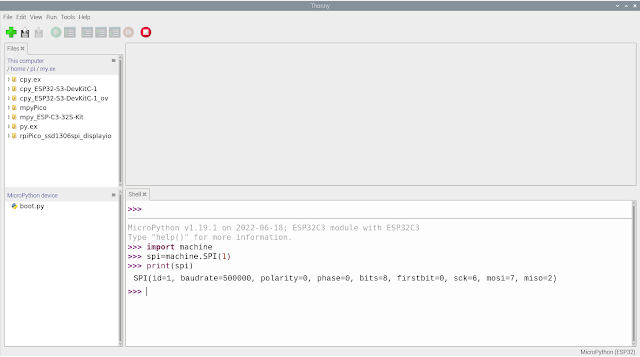
To list the default SPI pins in MicroPython: >>> import machine >>> spi=machine.SPI(1) >>> print(spi) SPI(id=1, baudrate=500000, polarity=0, phase=0, bits=8, firstbit=0, sck=6, mosi=7, miso=2) >>> Tested on ESP32C3:

MicroPython run tasks concurrently, base on time ticks, uasyncio and _thread.

Image
Exercises in last post " MicroPython/NodeMCU ESP-C3-32S-Kit control onboard LEDs " run tasks in one-by-one sequence. It call blocking function time.sleep() to delay, so the tasks cannot run in parallel. In this post, I run tasks (to adjust LEDs pwm) concurrently, base on time ticks, uasyncio and _thread. Based on time ticks mpy_NodeMCU_ESPC3_Blink_Without_Sleep.py """ MicroPython/NodeMCU ESP-C3-32S-Kit exercise to Change RGB LED (PWM) without calling time.sleep(). ref: MicroPython doc -time module https://docs.micropython.org/en/latest/library/time.html """ import os import sys import time from machine import Pin, PWM print() print("====================================") print(sys.implementation[0], os.uname()[3], "\nrun on", os.uname()[4]) print("========================...

MicroPython/NodeMCU ESP-C3-32S-Kit control onboard LEDs

Image
In NodeMCU ESP-C3-32S-Kit , there are Cool, Warm and a three-in-one RGB lamp on board. - IO3  : RGB red - IO4  : RGB green - IO5  : RGB blue - IO18 : Warm LED - IO19 : Cool LED Here is exercises to control ESP-C3-32S-Kit onboard LEDs in MicroPython: mpy_NodeMCU_ESPC3_RGB.py """ MicroPython/NodeMCU ESP-C3-32S-Kit exercise to control RGB LED. """ import uos import usys from machine import Pin import time # NodeMCU ESP-C3-32S-Kit onboard LEDs assignment pinR = Pin(3, Pin.OUT) pinG = Pin(4, Pin.OUT) pinB = Pin(5, Pin.OUT) pinWarm = Pin(18, Pin.OUT) pinCool = Pin(19, Pin.OUT) print() print("====================================") print(usys.implementation[0], uos.uname()[3], "\nrun on", uos.uname()[4]) print("====================================") while True: #All OFF pinR.value(0) pinG.value(0) pinB.value(0) pinWarm.value(0) pinCool.value(0) time.sleep(1) #tur...

MicroPython exercise implement class to do repeat task in fix-time delay, without blocking.

Image
In MicroPython, for convenience, we usually call time.sleep() to implement fix-time delay. But time.sleep() is blocking function, means it will not return until sleep time reached and block other opeeration. This exercise implement class to do repeat task in fix-time delay, without blocking. The code measure ticks difference between current time and expected time to determine is it time reached. It not, return control to next job. Such that you can do others while it's waiting. Tested on  NodeMCU ESP-C3-32S-Kit running MicroPython v1.19.1 . mpy_NodeMCU_ESPC3_delay_nosleep.py """ MicroPython exercise implement class to do repeat task in fix delay, without blocking. Tested on NodeMCU ESP-C3-32S-Kit ref: MicroPython time module: https://docs.micropython.org/en/latest/library/time.html """ import os import sys import time print() print("====================================") print(sys.implementation[0], os.uname()[3], ...

Install esptool on Raspberry Pi OS and flash MicroPython/CircuitPython firmware on NodeMCU ESP-C3-32S-Kit

Image
Updated@2024-01-28: In pre-bookworm Raspberry Pi OS, esptool can be install esptool directly, system-wide, using pip. This is no longer the case in the new Raspberry Pi OS (bookworm). From bookworm onwards, when using pip, packages must be installed into a Python virtual environment. Read:  Install esptool inside Virtual Environment, on Raspberry Pi 5 running 64-bit Raspberry Pi OS (bookworm) . This video show how to install esptool on Raspberry Pi OS 32 bit buster and flash MicroPython v1.19.1 firmware on NodeMCU ESP-C3-32S-Kit . (and also Espressif ESP32-S3-DevKitC-1 ) Install esptool.py using pip3 $ sudo pip3 install esptool To identify the USB connected to ESP-C3-32S-Kit before connected, clear dmesg with command $ sudo dmesg -c after connected, run dmesg again $ dmesg With esptool.py installed, you can check ESP chip with: $ esptool.py --chip auto --port /dev/ttyUSB0 chip_id $ esptool.py --chip auto --port /dev/ttyUSB0 flash_id To updeate espto...

my dev.board - NodeMCU ESP-C3-32S-Kit

Image
my dev.board - NodeMCU ESP-C3-32S-Kit: marked C3FN4, it's normal version with PCB onboard antenna, built-in 4M flash. (refer to section 3. Exterior in ESP-C3-32S-Kit Specification) ~  ESP-C3-32S-Kit Specification Related: ~  Install esptool on Raspberry Pi OS and flash MicroPython/CircuitPython firmware on NodeMCU ESP-C3-32S-Kit ~  Install Arduino IDE 1.8.19 on Raspberry Pi OS 32-bit buster, and setup arduino-esp32 ~  ESP32-C3(NodeMCU ESP-C3-32S-Kit) drive SSD1331 SPI Color OLED, in arduino-esp32 framework . ~  BLE UART Communication between ESP32-C3 (Xiao ESP32C3 and NodeMCU ESP-C3-32S-Kit) ~  BLE Remote Control between ESP32-S3/C3 using ArduinoBLE Library