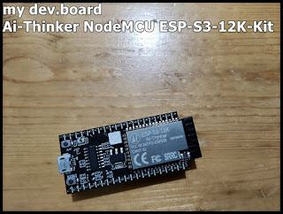
Drive 320x240 ILI9341 SPI TFT using ESP32-S3 (NodeMCU ESP-S3-12K-Kit) using TFT_eSPI library, in Arduino Framework.

Drive 2.4 inch 320x240 ILI9341 SPI TFT on Ai-Thinker NodeMCU ESP-S3-12K-Kit using TFT_eSPI library, in Arduino Framework. The steps same as in my former post " Drive ILI9341 (8-bit parallel) using ESP32-S3 (ESP32-S3-DevKitC-1) ", with custom user setup for SPI ILI9341 driver. The custom user setup I modify from is Setup70b_ESP32_S3_ILI9341.h (inside your local installed library folder or here ), copy it to the new created "TFT_eSPI_Setups" folder, rename as mySetup70b_ESP32_S3_ILI9341.h. For SPI connection, I follow the original assignment. For DC and RST pins, the original assigned pins (GPIO 7 and 6) are connected to LEDs in NodeMCU ESP-S3-12K-Kit (ref: ESP-S3-12K-Kit Schematic ), so I re-assign to GPIO 16 and 15). mySetup70b_ESP32_S3_ILI9341.h // Setup for the ESP32 S3 with ILI9341 display // Note SPI DMA with ESP32 S3 is not currently supported #define USER_SETUP_ID 70 // See SetupX_Template.h for all options available #def...