Posts

Showing posts from March, 2023

Generate QRCode with Raspberry Pi Pico (arduino framework), display on 1.54" 200x200 B&W e-Paper (SSD1681)

Image
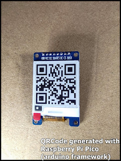
Last post show how to  display on 1.54" 200x200 e-Paper (SSD1681) with Raspberry Pi Pico using GxEPD2 library, in Arduino framework . It's another exercise to generate QRCode with Raspberry Pi Pico, and display on 1.54" 200x200 B&W e-Paper (SSD1681) GxEPD2 and QRCode libraries are needed, install them in Arduino IDE's Library Manager. Code Pico_GxEPD2_SSD1681_qrcode.ino /* *Exercise run on Raspberry Pi Pico/RP2040 *display QRCode on 1.54" 200x200 e-Paper with SSD1681 SPI driver, *using ZinggJM/GxEPD2 and qrcode lib * *qrcode: *https://github.com/ricmoo/qrcode/ */ #include <GxEPD2_BW.h> #include <qrcode.h> #define EPD_CS 17 #define EPD_DC 21 #define SRAM_CS -1 #define EPD_RESET 20 #define EPD_BUSY 22 GxEPD2_BW<GxEPD2_154_GDEY0154D67, GxEPD2_154_GDEY0154D67::HEIGHT> display( GxEPD2_154_GDEY0154D67(EPD_CS, EPD_DC, EPD_RESET, EPD_BUSY)); const int DISP_WIDTH = display.width(); const int D

Create shared folder between Windows host and Linux guest in VirtualBox

Image
Make sure Guest Additions CD image is installed. Click on VirtualBox Menu Devices > Shared Folders > Shared Folders Settings... In the pop-up box, locate the shared folder in host, enable Auto-mount and Make permanent options. The shared folder in guest Linux is on /media/sf_share_LinuxMint. But, permission not granted. To grant permission to user, enter: $ sudo usermod -a -G vboxsf <user> Then restart the guest Linux. DONE after restarted.

Display on 1.54" 200x200 e-Paper (SSD1681) with Raspberry Pi Pico using GxEPD2 library, in Arduino framework.

Image
To display on 1.54" 200x200 e-Paper (SSD1681 SPI) with Raspberry Pi Pico using GxEPD2 library, in Arduino framework. GxEPD2 library is needed, it can be installed in Arduino IDE Library Manager. Connection between Raspberry Pi Pico and SSD1681 SSD1681 e-Paper Raspberry Pi Pico ================================= BUSY 22 CS 17 DC 21 RES 20 SDA 19 (MOSI) SCL 18 (SCK) VCC 3V3 GND GND Code: Pico_GxEPD2_SSD1681_hello.ino, display text. /* *Exercise run on Raspberry Pi Pico/RP2040 *display on 1.54" 200x200 e-Paper with SSD1681 SPI driver, *using ZinggJM/GxEPD2 lib. * */ #include <GxEPD2_BW.h> #include <Fonts/FreeMonoBold9pt7b.h> #include <Fonts/FreeMono9pt7b.h> #define EPD_CS 17 #define EPD_DC 21 #define SRAM_CS -1 #define EPD_RESET 20 #define EPD_BUSY 22 GxEPD2_BW<GxEPD2_154_GDEY0154D67, GxEPD2_154_GDEY0154D67::HEIGHT> display( GxEPD2_154_GDEY0154D67(EPD_CS, EPD_DC, EPD_RESET, EPD_BUSY)); void setup()

Bluetooth serial communication between RP2040 using HC-04 Bluetooth Module, in BLE/SPP mode.

Image
Last post show a simple example of  Serial communication between two RP2040 (Arduino Framework) . With  HC-04 Dual Mode Bluetooth Module (SPP/BLE) , it's easy to implement bluetooth serial communication without change in code. For the Arduino code Serial_9600N81_SH1107.ino and SerialPassthrough_9600N81.ino, refer to last post . Setup Test Host (ttyACM0) Test Host (ttyACM1) | | +-----------+ +-------+ +-------+    +-----------+ |Slave      | |HC-04 | |HC-04 |    |Master | | TX|---|RX | Bluetooth |    RX|---|TX | | RX|---|TX |<~~~SPP/BLE~~~>|      TX|---|RX | | 3V3|---|VCC | |      VCC|---|3V3 | | GND|---|GND | |      GND|---|GND | |      | +-------+ +-------+    | | +-----------+      +-----------+ +-----------+ |SH1107 OLED| |     | +-----------+ WeAct RP2040 running      Raspberry Pi Pico running Serial_9600N81_SH1107.ino      SerialPassthrough_9600N81.ino

Serial communication between two RP2040 (Arduino Framework)

Image
These are simple examples to implement Serial Communication, between Raspberry Pi Pico and WeAct RP2040 with 128x128 SH1107 SPI OLED . Connection between two RP2040s +-----------------------------------+ | | |      +----------------------------------+ |      |           | | |      | +------------------------------------+ |      | |      | |    | |      | |           +---------------+    | |   | +---------------+ |      +-|-TX    GP0 | RPi Pico | | | +---TX GP0 | WeAct RP2040 | |      +-RX GP1 | | | +-------RX GP1 | | +------------GND | | +---------------GND | | |           | |           Connection: Raspberry Pi WeAct RP2040 Pico ============================ TX(GP0) RX(GP1) RX(GP1) TX(GP0) GND GND Example Code: SerialPassthrough_9600N81.ino, run on Raspberry Pi Pico. /* Serial (UART) exercise run on Raspberry Pi Pico/RP2040. Actually, it's from Arduino Examples > Communiction > Serial

HC-04 Bluetooth Module (SPP/BLE) and HC-T Test Adapter (USB-to-TTL converter)

Image
HC-04 Bluetooth serial communication module is a new generation of dual-mode digital transmission module based on classic Bluetooth SPP (V2.1) and BLE. ~ Product page ~ HC-04 Specification (v2.4) HC-T Test Adapter (USB-to-TTL converter) can be used with HC series modules. ~ Product page First Test HC-04 Bluetooth SPP/BLE Module It's my first test on HC-04: - A Raspberry Pi is used as test host, via RP2040 dev. board as USB-to-Serial adapter, connect to HC-04. HC-04 act as slave in default. - Test with AT-command. - And communicate with Android device with HC's Android Bluetooth Serial Assistant App, in BLE mode and Classic Bluetooth SPP mode. For the USB-to-Serial adapter implemented with RP2040, refer to the post  Serial communication between two RP2040 (Arduino Framework) . Both Serial_9600N81_SH1107.ino (with SH1107 OLED) and SerialPassthrough_9600N81.ino (without display) can be used. Connect RP2040 board with HC-04: HC-04

Display on 128x128 SH1107 SPI OLED with RP2040 (Arduino Framework) using U8g2 lib.

Image
Steps to setup library on Arduino IDE, to display on 1.12" 128x128 SH1107 SPI OLED with RP2040. Tested on WeAct RP2040 (16MB) . Run example, using suitable constructor and run. Library: Install U8g2 in Arduino IDE Library Manager.  U8g2 is a library for monochrome displays, version 2. Connection: Raspberry Pi Pico pre-defines SPI pins in Arduino are: SPI_MOSI:      19 SPI_MISO:      16 (not use) SPI_SCK:         18 Connection between RP2040 and SH1107 SPI OLED SH1107 RP2040 ================== GND GND VCC 3V3 SCL GP18 SDA GP19 RES GP20 DC GP21 CS GP22 Example: Open Examples > U8g2 > full_buffer > GraphicsTest In my test, Use one of the constructors: U8G2_SH1107_PIMORONI_128X128_F_4W_HW_SPI u8g2(U8G2_R0, /* cs=*/ 22, /* dc=*/ 21, /* reset=*/ 20); //U8G2_SH1107_SEEED_128X128_F_4W_HW_SPI u8g2(U8G2_R0, /* cs=*/ 22, /* dc=*/ 21, /* reset=*/ 20); Related: ~  Serial communication between two RP2040

Raspberry Pi Pico (in Arduino) get board info, include pins assignment.

Image
This simple code retrieve board info, include pre-defined pins assignment, for Raspberry Pi Pico (rp2040) in Arduino framewok. pico_pins_info.ino void setup() { delay(2000); Serial.begin(115200); delay(200); Serial.println("\n- Pico (rp2040) pins info -"); Serial.println("-----------------------------"); Serial.println("BOARD_NAME:\t\t" + String(BOARD_NAME)); Serial.println("BOARD_VENDORID:\t\t" + String(BOARD_VENDORID, HEX)); Serial.println("BOARD_PRODUCTID:\t" + String(BOARD_PRODUCTID, HEX)); Serial.println(); Serial.println("LED_BUILTIN:\t" + String(LED_BUILTIN)); Serial.println(":\t" + String()); Serial.println("SPI_MOSI:\t" + String(SPI_MOSI)); Serial.println("SPI_MISO:\t" + String(SPI_MISO)); Serial.println("SPI_SCK:\t" + String(SPI_SCK)); Serial.println(); Serial.println("I2C_SDA:\t" + String(I2C_SDA)); Serial.println("I

RP2040/CircuitPython display on SH1107 SPI OLED

Image
Exercise of using WeAct RP2040 (16MB) with CircuitPython 8.0.4  to display on 1.12" 128x128 SH1107 SPI OLED . Connection      SH1107 RP2040      ==================      GND           GND      VCC           3V3      SCL           GP10      SDA           GP11      RES           GP13      DC           GP14      CS           GP15 Prepare Library Visit https://circuitpython.org/libraries , download CircuitPython Libraries Bundle for Version 8.x. Upload adafruit_display_text adafruit_display_shapes folders, and adafruit_displayio_sh1107.mpy to CircuitPython device's /lib. Exercise Code cpyRP_SH1107_hello.py """ Exercise run on WeAct RP2040 (16MB)/CircuitPython 8.0.4 To driver 1.12" 128x128 SH1107 SPI OLED ref: https://docs.circuitpython.org/projects/displayio-sh1107/en/latest/ I call adafruit_displayio_sh1107.SH1107() with display_offset=adafruit_displayio_sh1107.DISPLAY_OFFSET_ADAFRUIT_128x128_OLED_5297. It's by trying. If it

CircuitPython on WeAct RP2040 Dev. Board (16M Flash)

Image
To install CircuitPython on  WeAct RP2040 Dev. Board , visit CircuitPython Download Page , search and install "WeAct Studio Pico (16MB Variant) by WeAct Studio" . Total space is reported 15 MB. Related: ~  RP2040/CircuitPython display on SH1107 SPI OLED

1.12" 128x128 SH1107 SPI OLED

Image
 my display module: 1.12" 128x128 SH1107 SPI OLED ~ product page Exercise: ~  RP2040/CircuitPython display on SH1107 SPI OLED ~  Display on 128x128 SH1107 SPI OLED with RP2040 (Arduino Framework) using U8g2 lib ~  Serial communication between two RP2040 (Arduino Framework)

Display on 1.28" 240x240 Round IPS LCD (with GC9A01 SPI driver) with ESP32 (arduino-esp32) using GFX Library for Arduino (Arduino_GFX)

Image
Display on 1.28" 240x240 Round IPS LCD (with GC9A01 SPI driver) with ESP32-DevKitC V4 (arduino-esp32) using GFX Library for Arduino (Arduino_GFX) Install GFX Library for Arduino (Arduino_GFX) in Arduino IDE's Library Manager. Arduino_GFX is a Arduino graphics library supporting various displays with various data bus interfaces. Open File > Examples > GFXLibrary for Arduino > HelloWorld Comment the original Arduino_GFX setting, and replace with my custom setting for GC9A01, matching with my connection.  Modified HelloWorld.ino is listed here for reference. /******************************************************************************* * Start of Arduino_GFX setting * * Arduino_GFX try to find the settings depends on selected board in Arduino IDE * Or you can define the display dev kit not in the board list * Defalult pin list for non display dev kit: * Arduino Nano, Micro and more: CS: 9, DC: 8, RST: 7, BL: 6, SCK: 13, M

1.28" 240x240 GC9A01 SPI IPS on RP2040/MicroPython, using russhughes/gc9a01py lib.

Image
It's ZhongJingYuan 1.28" 240x240 Round IPS LCD with GC9A01 , on WeAct RP2040 (16MB) with MicroPython v1.19.1, using russhughes/gc9a01py library. Library: To prepare Library (russhughes/gc9a01py library), visit: https://github.com/russhughes/gc9a01py . Upload lib, fonts and examples folders to MicroPython device's / Connection: GC9A01 RP2040 -------------------------- BLK GP26 CS GP22 DC GP21 RES GP20 SDA GP19 SCL GP18 VCC 3V3 GND GND Code: Modify the examples code as shown in the video above. Modified hello.py is listed here for reference. hello.py """ hello.py Writes "Hello!" in random colors at random locations on the display """ import random from machine import Pin, SPI import gc9a01py as gc9a01 # Choose a font # from fonts import vga1_8x8 as font # from fonts import vga2_8x8 as font # from fonts import vga1_8x16 as font # from fonts import vga2_8x16 as font # from fonts import vga1_16x16

ZhongJingYuan 1.28" 240x240 Round IPS LCD - GC9A01 SPI driver

Image
ZhongJingYuan 1.28" 240x240 Round IPS LCD with GC9A01 SPI driver ~ product page Exercises: ~  1.28" 240x240 GC9A01 SPI IPS on RP2040/MicroPython, using russhughes/gc9a01py lib . ~  Display on 1.28" 240x240 Round IPS LCD (with GC9A01 SPI driver) with ESP32 (arduino-esp32) using GFX Library for Arduino (Arduino_GFX)

WeAct RP2040 Dev. Board (16M Flash)

Image
It's WeAct Studio version of Raspberry Pi Pico (RP2040), available in 2MB/4MB/8MB/16MB of onboard Flash memory. Mine is 16MB version. Pinout: Links ~ WeActStudio/WeActStudio.RP2040CoreBoard To verify that MicroPython run on WeAct RP2040 report 16M storage: Exercises: MicroPython ~  1.28" 240x240 GC9A01 SPI IPS on RP2040/MicroPython, using russhughes/gc9a01py lib . CircuitPython ~ In case of CircuitPython, download and  install CircuitPython for "WeAct Studio Pico (16MB Variant) by WeAct Studio" . ~  RP2040/CircuitPython display on SH1107 SPI OLED ~  Raspberry Pi Pico/CircuitPython display on SSD1327 grayscale OLED ~  ILI9341 (8bit parallel bus) display on RP2040/CircuitPython ~  RP2040/CircuitPython 8.1.0 Beta 1, play animated GIF on 8 bit parallel bus ILI9341 . ~  Play animated GIF stored in SD Card ~  2.13" 250x122 e-paper (ssd1680) displayed on Raspberry Pi pico/CircuitPython ~  SSD1306 I2C OLED + 4X4 Matrix Keypa

Min. exercises to display on 2.13" 250x122 3-color E-paper with ESP32-S3, using GxEPD2 and Adafruit_EPD

Image
In my former posts, show how to install library and run example to display on 2.13" 250x122 3-color Epaper with ESP32-S3, using GxEPD2 and Adafruit_EPD . Here is my minimum exercise using GxEPD2 and Adafruit_EPD libraries respectively. ESP32_GxEPD2_SSD1680.ino , using ZinggJM/GxEPD2 library. /* *Minimum exercise using ZinggJM/GxEPD2 *Run on ESP32 Dev Module *display on 2.13" 250x122 3-color E-paper (SSD1680) * * ref: GxEPD2_MinimumExample.ino * https://github.com/ZinggJM/GxEPD2/blob/master/examples/GxEPD2_MinimumExample/GxEPD2_MinimumExample.ino * */ #include <GxEPD2_3C.h> // including both doesn't use more code or ram #include <Fonts/FreeMonoBold9pt7b.h> #define EPD_CS 5 #define EPD_DC 0 #define SRAM_CS -1 #define EPD_RESET 2 #define EPD_BUSY 15 GxEPD2_3C<GxEPD2_213_Z98c, GxEPD2_213_Z98c::HEIGHT> display( GxEPD2_213_Z98c(EPD_CS, EPD_DC, EPD_RESET, EPD_BUSY)); void setup() { display.init(); display.setRotatio

nanoCH32V003: 32-bit RISC-V dev. board

Image
nanoCH32V003 , a very cheap 32-bit RISC-V development board made by MuseLab based on WCH CH32V003F4U6, cost me RMB ¥6.8 only. related links: ~ Github: wuxx/nanoCH32V003 ~ WCH: 32-bit general-purpose RISC-V MCU-CH32V003 Related post: ~  Program CH32V003 with WCH-LinkE using MounRiver Studio on Windows 11 ~  CH32V003 UART example In Arduino Framework: ~  Install Core library for CH32duino (1.0.3) on Arduino IDE 2 to develop CH32 RISC-V MCU in Arduino Framework

ESP32-S3/CircuitPython act as socket client, connect to HC-25 WiFi Module.

Image
It's my CircuitPython 8.1.0 Beta 0 exercise run on Espressif ESP32-S3-DevKitC-1 , to act as WiFi station/socket client connect to socket server on HC-25 WiFi Module . cpyESP32S3_client.py import os import sys import time import wifi import socketpool import ipaddress ssid = "myHC-25" password = "password" serverAddr = "192.168.4.1" serverPort = 8080 print("=================================================") info = sys.implementation[0] + ' ' + os.uname()[3] + '\n' + \ 'run on ' + os.uname()[4] print(info) print("=================================================") print("Connect to network") # In my trial, most time wifi.radio.connect() raise: # ConnectionError: No network with that ssid # So I implement re-try here. connErrIcon = True while True: time.sleep(0.5) try: wifi.radio.connect("myHC-25","password") break except ConnectionErro

Play animated GIF in CircuitPython 8.1.0 Beta 0, run on ESP32-S3, display on ST7789 SPI TFT.

Image
In CircuitPython 8.1.0 Beta 0, animated GIF is supported with gifio.OnDiskGif. ~ ref:  Release Notes for 8.1.0-beta.0 It's a exercise to play GIFs running on Espressif ESP32-S3-DevKitC-1 (flashed with CircuitPython 8.1.0-beta.0), display on 1.14" 135x240 (RGB) IPS ST7789V SPI . To setup library and connection, refer to last post  ESP32-S3/CircuitPython 8 display on ST7789 SPI TFT . Exercise Code cpyS3_st7789_gif.py """ CircuitPython exercise run on ESP32-S3, to display GIFs on IPS with ST7789 SPI driver. dev. board: ESP32-S3-DevKitC-1-N8R8 CircuitPython: Adafruit CircuitPython 8.1.0-beta.0 on 2023-03-01 Tested IPS: - 1.14" 135x240 (RGB) IPS - 1.54" IPS 240x240 (RGB) - 2.0" IPS 240(RGB)x320 """ import os, sys import board import busio import terminalio import displayio import adafruit_st7789 import time import gifio # Release any resources currently in use for the displays displayio.release_displays()

ESP32-S3/CircuitPython 8 display on ST7789 SPI TFT

Image
It's a exercise run on Espressif ESP32-S3-DevKitC-1 flashed with CircuitPython 8.1.0-beta.0 to display on various ST7789 SPI TFT IPS display. -  1.14" 135x240 (RGB) IPS ST7789V SPI -  1.54" IPS 240x240 with SPI ST7789 driver -  2 inch 240x320 ST7789 SPI IPS TFT Prepare Library Visit https://circuitpython.org/libraries , download Bundle for Version 8.x. Extract the downloaded file. Upload adafruit_display_text folder and adafruit_st7789.mpy to CircuitPython device /lib folder. Connection ST7789 ESP32-S3 ================ BLK IO4 CS IO5 DC IO6 RES IO7 SDA IO15 SCL IO16 VCC 3V3 GND GND Exercise code cpyS3_st7789_testcolor.py """ CircuitPython exercise run on ESP32-S3, to display on IPS with ST7789 SPI driver. dev. board: ESP32-S3-DevKitC-1-N8R8 CircuitPython: Adafruit CircuitPython 8.1.0-beta.0 on 2023-03-01 Tested IPS: - 1.14" 135x240 (RGB) IPS - 1.54" IPS 240x240 (RGB) - 2.0" IPS 240(RGB)x320 "

1.54" IPS 240x240 with SPI ST7789 driver

Image
It's 1.54" IPS 240x240 with SPI ST7789 driver, by JhongJingYuan ~ Product Page Exercises: ~  ESP32-S3/CircuitPython 8 display on ST7789 SPI TFT ~  Play animated GIF in CircuitPython 8.1.0 Beta 0, run on ESP32-S3, display on ST7789 SPI TFT . ~  ESP32-S3/CircuitPython act as socket client, connect to HC-25 WiFi Module .