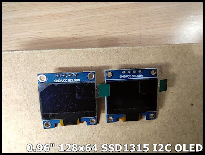
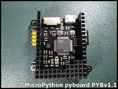
Pyboard/MicroPython display on SSD1315 I2C OLED using SSD1306 driver

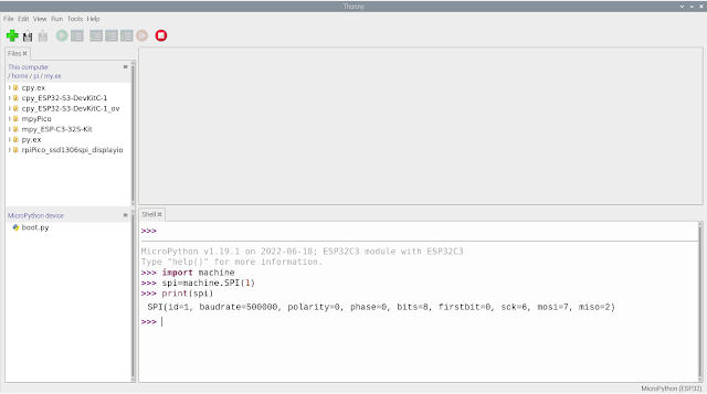
This video show how Pyboard PYBv1.1 ( flashed with MicroPython v1.19.1 ) display on 0.96 inch 128x64 SSD1315 I2C OLED using micropython-ssd1306 driver. The post " Raspberry Pi Pico/MicroPython exercise using SSD1306 I2C OLED " show how to manual install ssd1306 driver to MicroPython device. This video show another approach in Thonny to install micropython-ssd1306 driver . This is a fork of the driver for SSD1306 displays which is hosted in the Micropython package . The purpose of this fork is to make the driver available on PyPi and thus installable via the upip package manager. But it haven't implemented rotate() function. Exercise code mpyPYB_i2c_scanner.py Show I2C info and scan I2C devices import sys import os import machine print("====================================") print(sys.implementation[0], os.uname()[3], "\nrun on", os.uname()[4]) print("====================================") print...